Motivation & Research Question
Hands-free control of robots is underexplored relative to traditional handheld controllers, despite the potential it has to advance human-robot interaction — for anyone whose hands are occupied, or unavailable, a torso-driven interface is a genuinely different way to command a machine, not just a novelty. This work presents a torso-based navigation framework for a simulated mobile robot in a virtual environment, driven by torso motion signals captured from the Torso-dynamics Estimation System (TES). The question the whole study is built around: how effectively can torso motion signals, captured by different sensor configurations, be used to control a virtual robot in a structured VR environment?
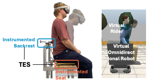
Fig. 1 — hands-free control of a virtual rider on an omnidirectional robot, using signals from the TES (an instrumented backrest and instrumented seat measuring rotation and translation of the body).
Custom Hardware
The TES hardware was designed and fabricated in-house by members of the Human Dynamics and Controls Lab. The instrumented seat measures reactive moments in the sagittal and frontal planes via four uniaxial load cells (FRC4142_0, Phidgets, Canada), while the instrumented backrest measures rotational displacement about the vertical axis using a potentiometer, allowing free translational movement in the X and Y directions at the same time. Together the two produce the three-element reference vector used for robot command generation — the seat's frontal- and sagittal-plane moments (Mx, My) computed from the four load-cell readings (F₀–F₃) as:
My = a(−F₀ + F₁ + F₂ − F₃)
Mx = b(F₀ + F₁ − F₂ − F₃)
FR = F₀ + F₁ + F₂ + F₃
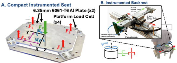
Fig. 2 — (A) four load cells integrated into the seat record reactive moments (Mₓ, Mᵧ). (B) the instrumented backrest allows free X/Y translation while a potentiometer measures yaw.
Mapping Virtual & Physical Environments
Four input configurations were implemented and compared: a hands-on joystick (JS) as the baseline, and three hands-free embodiments — an IMU alone (VN-100, VectorNav Technologies, USA), an instrumented seat with IMU (S+IMU), and an instrumented seat with a backrest-mounted sensor (S+BR). Each configuration produces its own three-element reference vector encoding two translational and one rotational torso signal, which then passes through a dead-zone filter, a first-order FIR smoother, an adjustable gain, and output saturation to yield the final velocity commands (vx, vy, ωz) sent to the virtual robot.
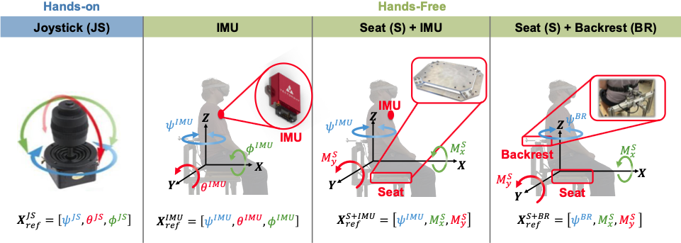
Fig. 3 — the four input configurations compared: hands-on joystick (JS), and three hands-free embodiments (IMU-only, seat+IMU, seat+backrest).
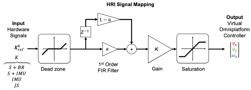
Fig. 4 — signal processing pipeline mapping input hardware signals to platform control commands: dead-zone filtering, first-order FIR filtering, gain adjustment, and output saturation.
Virtual Course Design
To evaluate navigation performance in a realistic setting, a VR course was built in CoppeliaSim and modeled on U.S. Building Code standards — standard hallway widths, doorways, restroom layouts, and a mix of static and dynamic obstacles — so the comparison reflects built-environment navigation rather than an artificial test track. Wearing a VR headset while seated on the TES, the participant sees and navigates this CoppeliaSim-built course directly, steering the virtual omnidirectional robot through it using nothing but their torso motion.

Fig. 5 — virtual training (A) and testing (B) courses, built to U.S. Building Code standards.
Evaluation — System Validation
Before running the comparison itself, the TES signal pipeline had to be trusted. VN-100 IMU orientation output was checked against a Qualisys motion-capture system, and TES seat moment signals were checked against an AMTI force plate, across a series of controlled torso movements. Results confirmed sufficient tracking accuracy across all axes to enable reliable robot command generation — the custom hardware measures what it's supposed to measure, closely enough to build a control study on top of it.
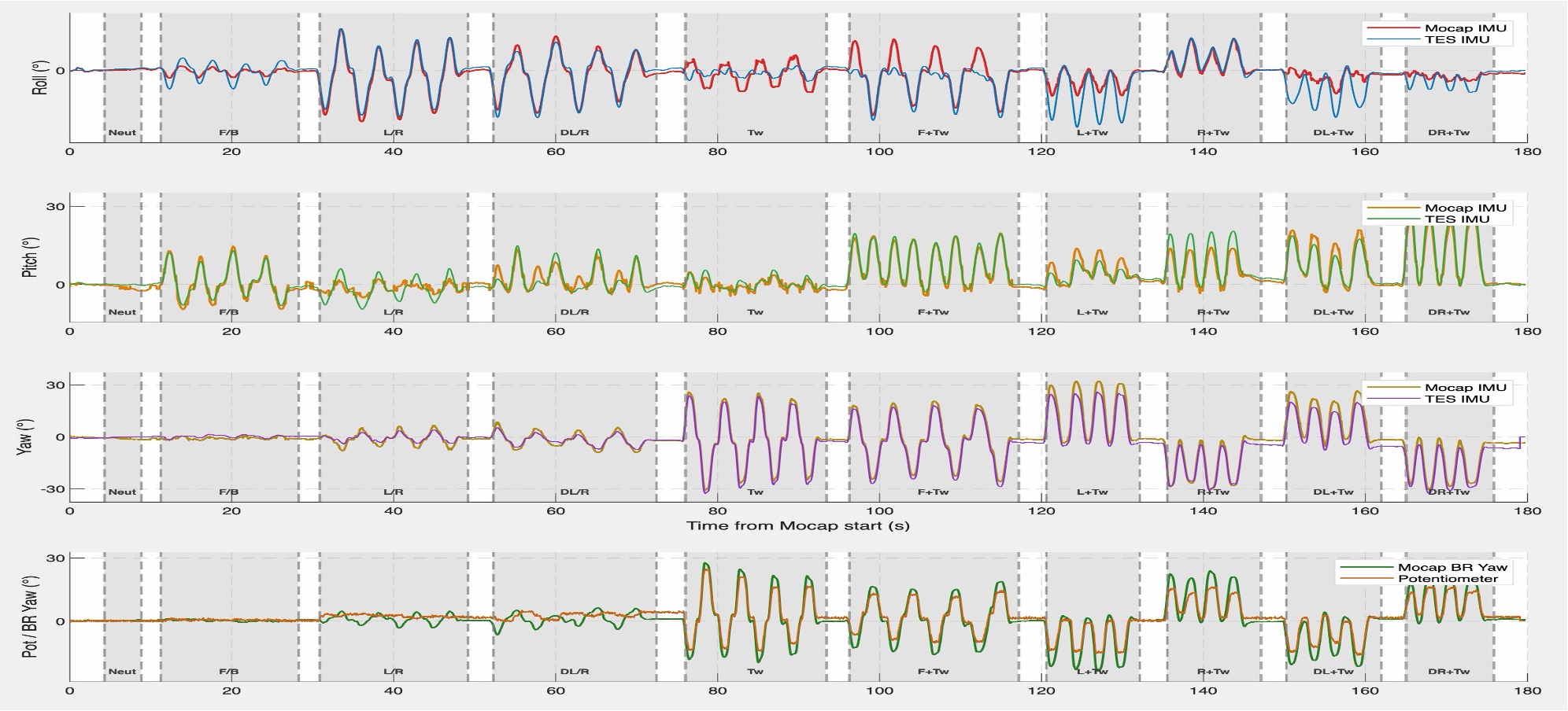
Fig. 6 — TES vs. Qualisys motion-capture signals across a structured sequence of torso movements: roll, pitch, and yaw (IMU vs. mocap) on top, backrest yaw (potentiometer vs. mocap markers) on the bottom. Shaded regions mark individual trials.
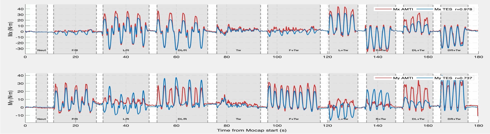
Fig. 7 — TES vs. AMTI force-plate seat moment signals over the same trial sequence: sagittal (Mₓ, top) and frontal (Mᵧ, bottom) plane moments.
Planned Experiment
With the hardware validated, the next step is the human study the whole framework was built for: participants will complete the VR test course under all four input conditions (joystick, IMU, S+IMU, and S+BR) with a familiarization trial on the training course (Fig. 5) before each condition, to minimize learning effects carrying over between conditions. The primary outcome measures are task completion time and collision count, both compared against the joystick baseline, to actually answer whether, and which, hands-free torso control holds up against the traditional handheld standard.
Presentations & Demo
An earlier version of this system was presented at the IMMERSE Symposium (Center for Immersive Computing) in 2025, as a poster with a live demo: people could sit on the TES, put on the headset, and steer the virtual robot through the CoppeliaSim course, with the simulator running on the monitor beside them.
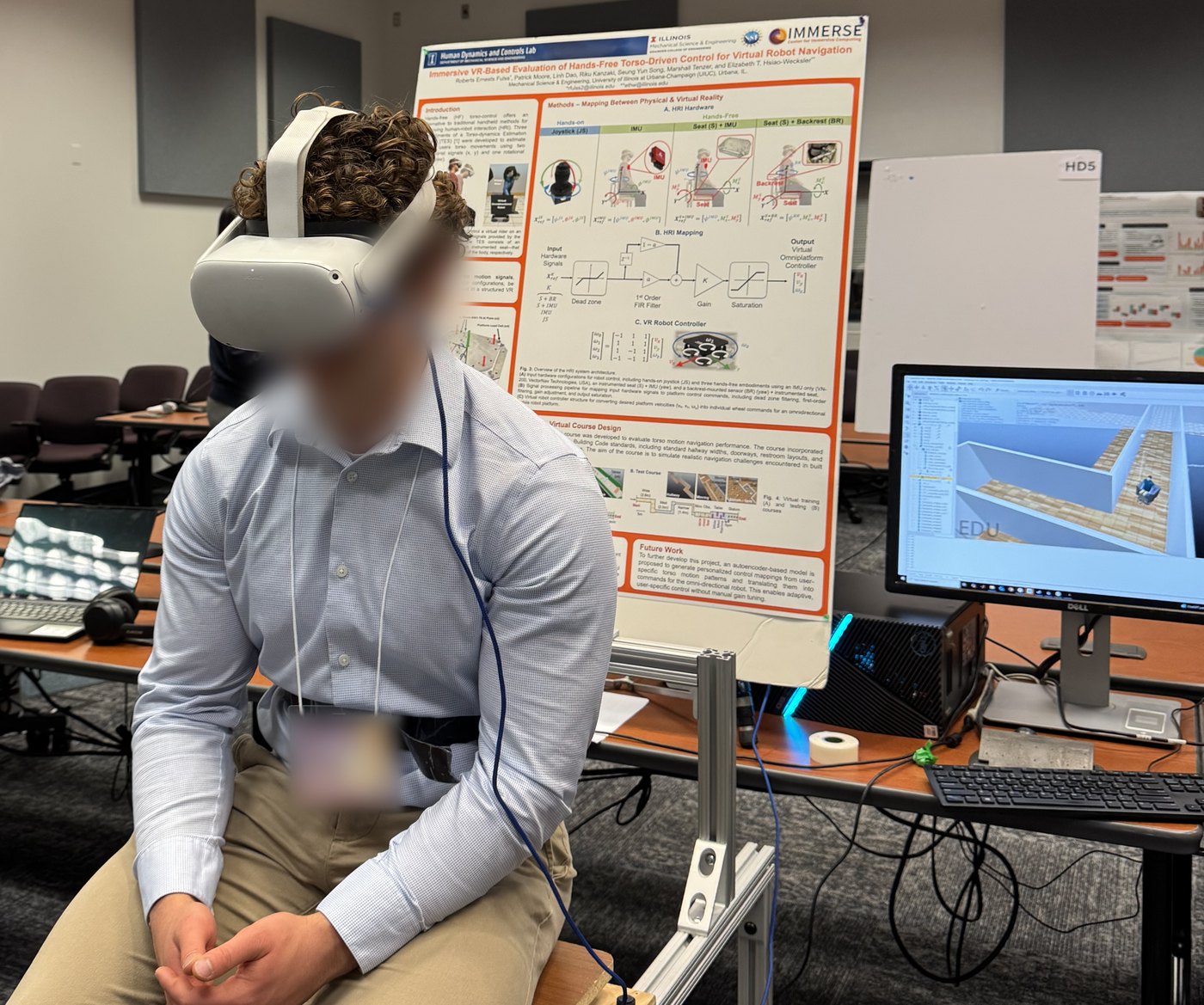
Live demo at the IMMERSE Symposium 2025, on the earlier prototype rig: a participant seated on the TES steers the virtual robot while the CoppeliaSim course runs on the monitor at right.
That first version was an earlier prototype: its backrest measured yaw with an absolute encoder and it used a VectorNav VN-200 IMU, whereas the version described above uses the potentiometer-instrumented backrest and a VN-100. The IMMERSE poster also covered a piece not described above — the virtual robot's controller, which converts the desired platform velocities (vx, vy, ωz) into individual wheel commands for the omnidirectional base through a fixed 4×3 matrix of ±1 coefficients — and proposed a next step: an autoencoder-based model that learns personalized control mappings from each user's own torso-motion patterns, removing the need for manual gain tuning.
Acknowledgements
Supported by NSF NRI Grant #2024905. TES hardware design credit to Riku Kanzaki, Marshall Tenzer, Linh Dao, Seung Yun Song, and Patrick Moore. The TES itself is the subject of a separate U.S. patent application (S. Y. Song et al., patent pending).