The Design
A cycloidal-style reducer gets its large reduction from an eccentrically driven, lobed disc that rolls around the inside of a ring, rather than from meshing gear teeth — which is what lets a compact package carry a lot of torque, with many surfaces sharing the load at once. This build pairs that reduction stage with a brushless DC motor. The CAD cross-section below shows the internal layout: two discs stacked on a common axis, each carried on bearings, with the motor seated in a cage at the back and the output plate at the front.
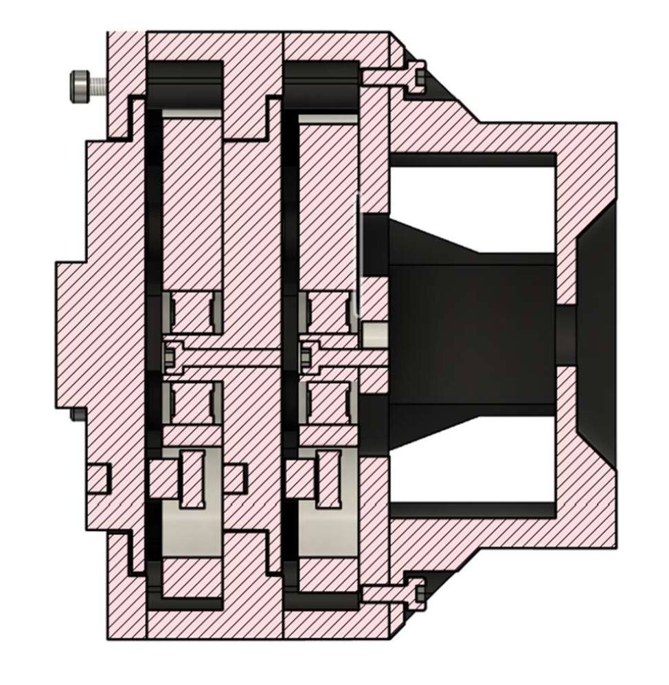
Fig. 1 — CAD cross-section: two discs stacked on a common axis, each on bearings, with the motor cage at right and the output plate at left.
The gears are 3D printed. Laid out flat, the build is easy to read: the brushless motor and its 30 A speed controller (top left), the black housing and motor cage, the two cycloidal discs each with a bearing at its center, and the two output plates with their bolts.
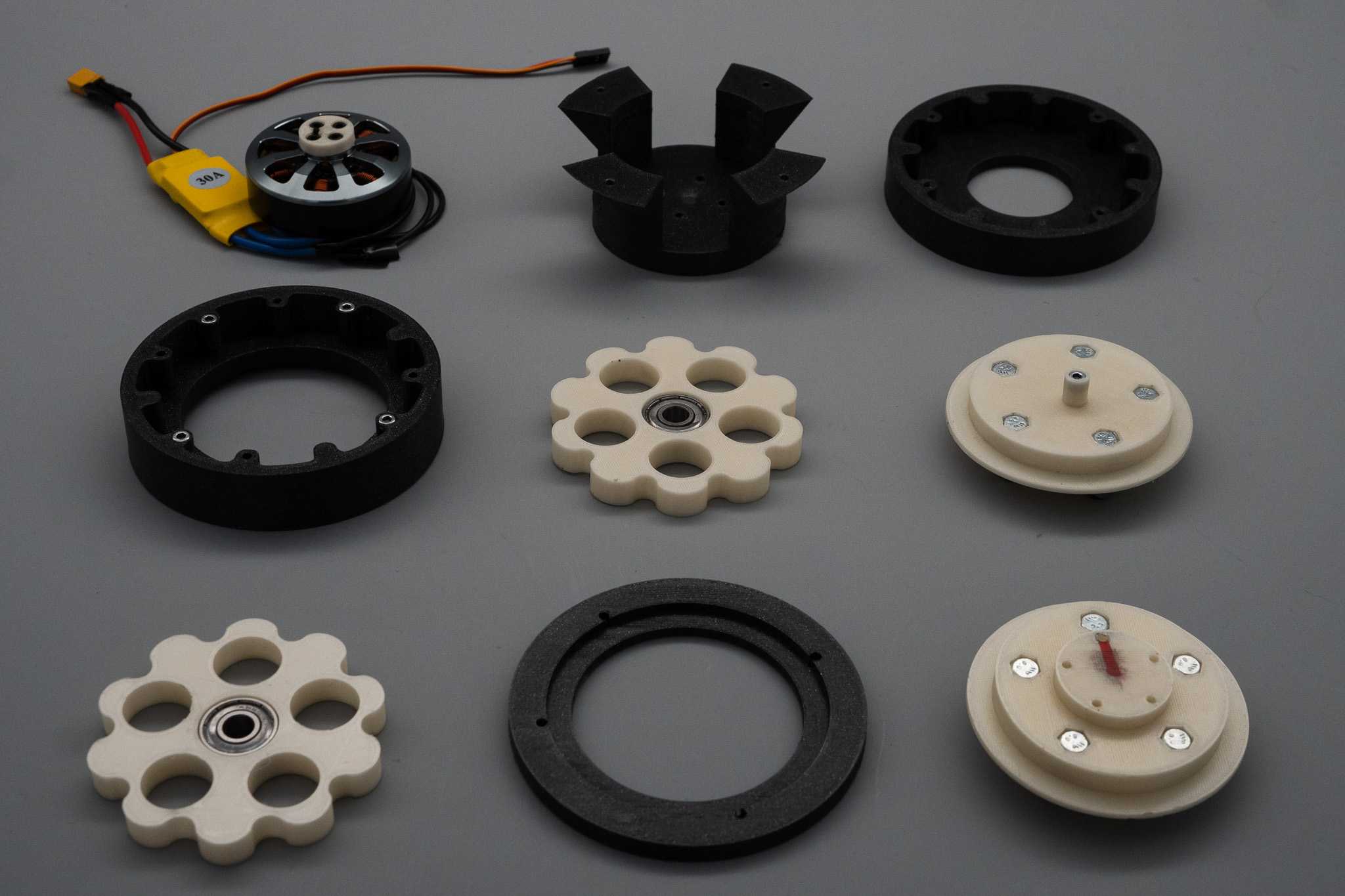
Fig. 2 — the full parts set: brushless motor and 30 A controller, black housing pieces, two cycloidal discs on bearings, and output plates.
Making Printed Parts Last
A fully printed gear train wears quickly precisely where surfaces slide and press against each other. So at the contact points, the design uses bearings and cut metal rods instead of bare plastic — keeping the light, cheap, easily re-printed structure, while giving relatively high wear resistance where it matters. Below, each disc sits in its ring housing with a bearing at its center.
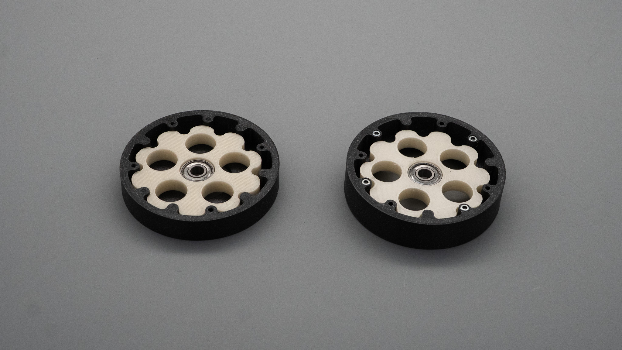
Fig. 3 — each cycloidal disc seated in its ring housing, bearing at the center (output plate removed).
Cost
The gearbox and the motor together cost approximately $50 — about 15% of the industry standard. The gears are 3D printed, and the bearings and metal rods at the contact points are there so that the low cost doesn't come at the expense of wear resistance.
Sensing & Control
To control the output shaft, a hall-effect sensor is attached to the drive shaft and read over the I²C communication protocol. Because the sensor sits on the fast, input side of the reduction, each measured degree of drive-shaft rotation corresponds to a much smaller movement at the output, which helps make fine positioning practical. The result: the output shaft could be controlled to about 0.5° accuracy.
Testing
Torque was tested on a simple bench rig, shown below: the gearbox zip-tied into a wooden cradle clamped to the bench, and a long lever arm attached to the output shaft pressing on a digital scale — the standard lever-and-scale method, where torque is the lever length times the force on the scale. The gearbox reliably delivers about 20 Nm.
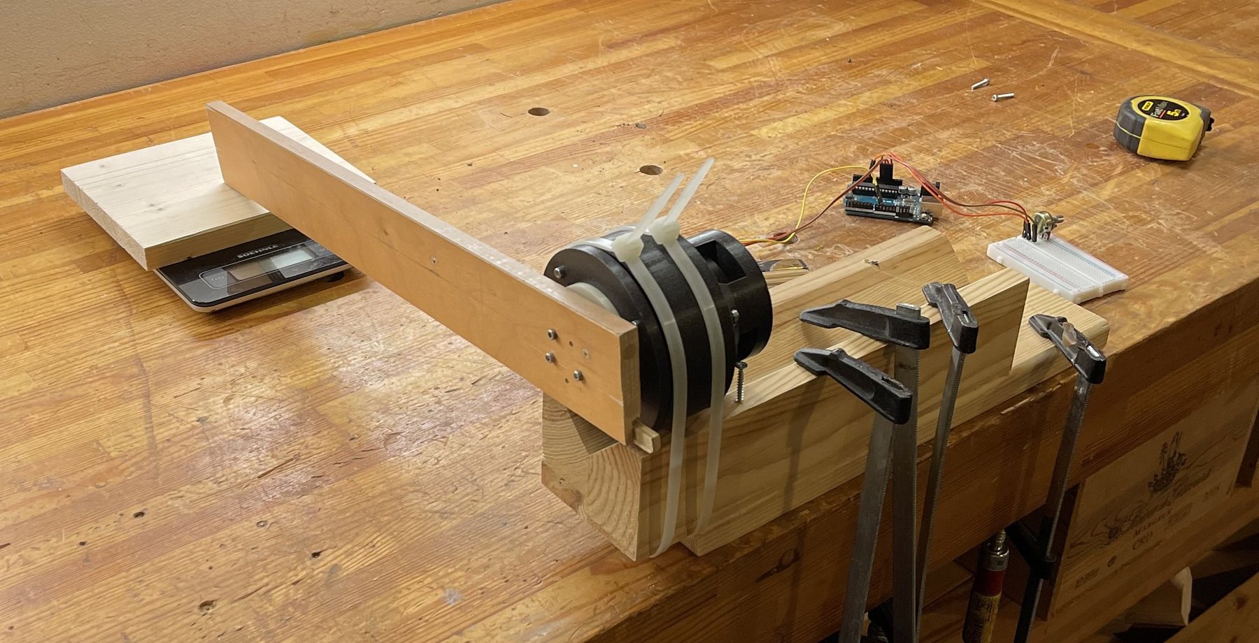
Fig. 4 — bench torque-test rig: gearbox clamped in a wooden cradle, lever arm on the output shaft pressing on a digital scale, Arduino and breadboard alongside.